
When a fiberglass rod fails before its expected service life ends, the costs go beyond replacing the component. You face unplanned downtime, potential safety concerns, and questions about whether your specification was correct in the first place. Root-cause analysis helps you move past guesswork and identify exactly what happened—and why.
This guide walks you through a practical, field-to-lab workflow for investigating premature failure of fiberglass rods. Tencom delivers custom pultruded fiberglass rods engineered for specific mechanical and environmental requirements, and understanding failure modes helps you specify materials that last longer in your application.

You'll learn how to map exposure conditions, conduct visual inspections, and select the right confirmatory tests for UV degradation, moisture absorption, chemical attack, and fatigue damage.
By the end of this guide, you'll have a systematic approach to diagnosing failures and the knowledge to prevent them from recurring in future installations.
Key Takeaways: Fiberglass Rod Failure Analysis and Testing in 2026
- Premature fiberglass rod failure typically stems from UV degradation, moisture absorption, chemical exposure, or fatigue loading—often in combination.
- A systematic field-to-lab workflow helps you pinpoint the root cause rather than making assumptions based on visible damage alone.
- Tencom offers custom research and testing capabilities that help match resin systems and fiber reinforcements to your specific operating environment.
- Visual inspection checklists combined with targeted ASTM-aligned tests deliver actionable data for specification improvements.
- Proper exposure mapping before failure analysis ensures you capture all environmental factors that contributed to premature degradation.
What Causes Premature Fiberglass Rod Failure?
Fiberglass rods fail when the resin matrix, glass fiber reinforcement, or fiber-matrix interface degrades beyond acceptable limits. Understanding the primary failure mechanisms helps you focus your investigation on the most likely causes.
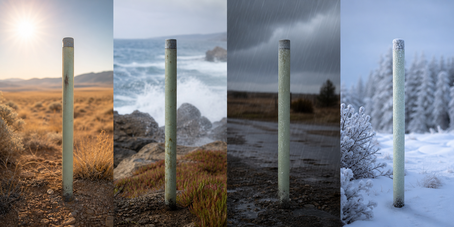
The four major categories of premature failure include UV degradation, moisture absorption, chemical attack, and mechanical fatigue. Each leaves a distinct signature that guides your diagnostic approach. Environmental factors rarely act alone—most real-world failures involve multiple stressors working together.
Your investigation should start with a clear picture of the service environment before examining the failed component. This context shapes everything that follows in your root-cause analysis.
How UV Radiation Damages Pultruded Fiberglass Rods
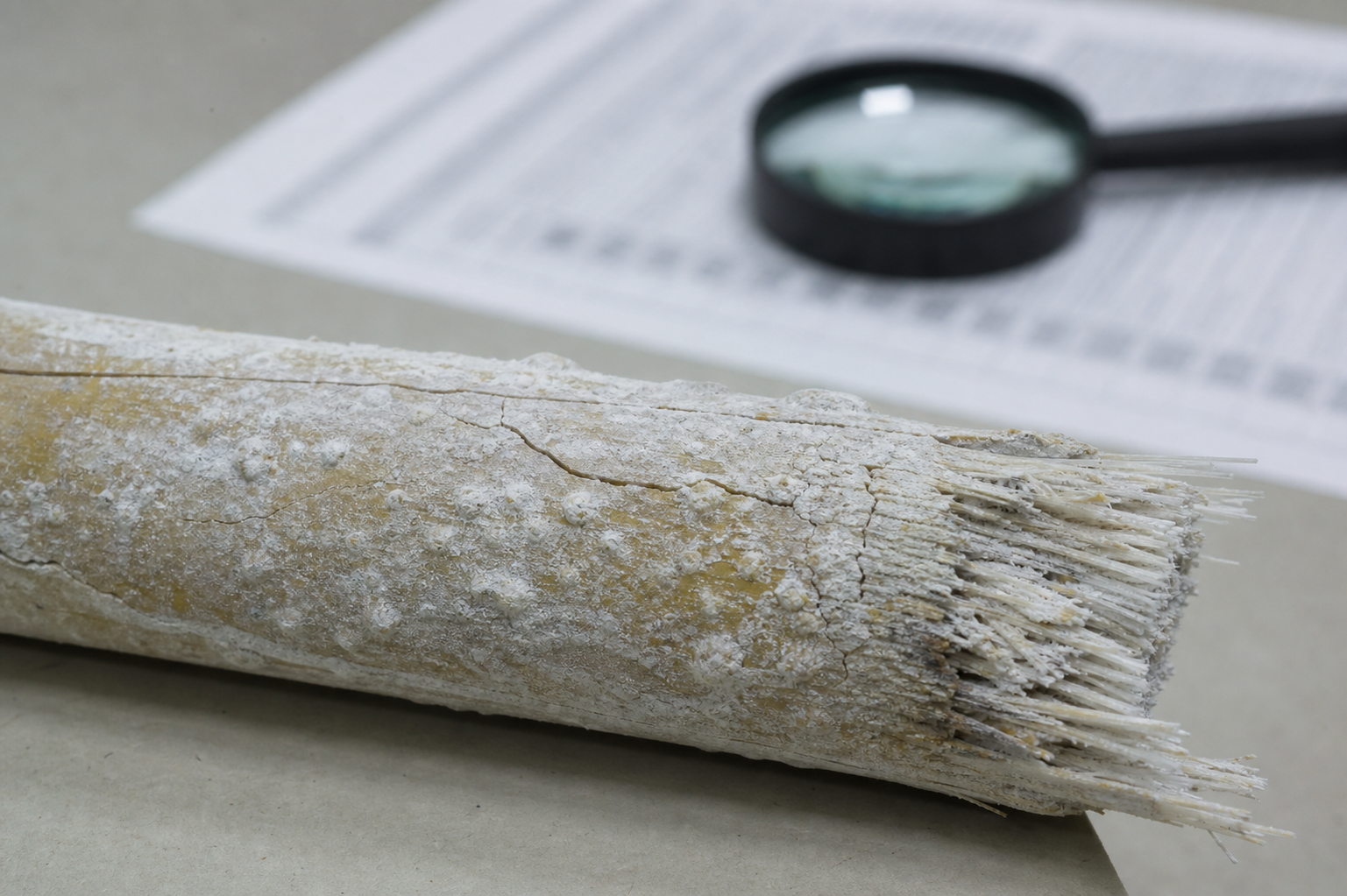
UV radiation breaks down polymer chains in the resin matrix, causing surface degradation that progresses inward over time. The visible symptoms include chalking, color fading, and a condition called "fiber bloom," in which the surface resin erodes and exposes glass fibers.
Surface degradation from UV exposure doesn't immediately compromise structural integrity. However, exposed fibers create entry points for moisture and chemicals. This secondary damage often significantly accelerates failure rates.
According to research published in Frontiers in Materials, UV-stabilized resin systems and surface veils can dramatically extend service life in outdoor applications. Selecting the right resin formulation for your exposure conditions is your first line of defense against UV-related failure.
How Moisture Absorption Weakens Fiberglass Composites
Moisture enters the composite through diffusion, particularly at cut ends, drilled holes, and microcracks in the resin surface. Once inside, water molecules cause plasticization of the polymer matrix, reducing the glass transition temperature and mechanical properties.
The fiber-matrix interface is especially vulnerable. Water hydrolyzes the chemical bond between glass fibers and resin. This interface degradation reduces load transfer efficiency and can cause delamination under stress.
Temperature accelerates moisture absorption rates. Components in warm, humid environments or those subject to thermal cycling absorb moisture faster and undergo more severe property degradation than those in stable, dry conditions.
How Chemical Exposure Causes Fiberglass Rod Degradation
A chemical attack targets the resin matrix directly. Acids, alkalis, solvents, and industrial fluids can penetrate the surface and cause matrix cracking, swelling, or dissolution depending on the specific chemistry involved.
Resin selection matters enormously for chemical exposure. Vinyl ester resins outperform polyester resins in most acidic and alkaline environments. Epoxy systems offer advantages in specific solvent applications. Matching your resin system to your chemical environment prevents many premature failures.
Splash zones and vapor exposure create different failure patterns from full immersion. Your exposure mapping should capture not just which chemicals are present, but how the component contacts them and for how long.
How Cyclic Loading Leads to Fiberglass Fatigue Failure
Fatigue damage accumulates through repeated loading cycles, even when individual loads remain well below the material's ultimate strength. Microscopic cracks initiate in the matrix, link together, and eventually cause delamination or fiber fracture.
The progression typically follows a pattern: matrix cracking appears first, followed by crack coupling between plies, then delamination growth, and finally fiber breakage. Catching fatigue damage early in this sequence allows for repair or replacement before catastrophic failure.
Stress concentrations around holes, notches, and connection points accelerate fatigue damage. Proper design of interfaces and load transfer zones considerably extends fatigue life.
How to Map Exposure Conditions Before Failure Analysis
Accurate exposure mapping creates the foundation for effective root-cause analysis. Without understanding what the component actually experienced in service, you're left guessing about which tests to run and how to interpret results.
Start by documenting the installation location, orientation, and service duration. Note any protective measures that were applied, such as coatings, covers, or controlled environments. Identify all potential stressors, including weather, chemicals, temperature extremes, and loading patterns.
Talk to operations personnel who work with the equipment daily. They often notice early warning signs or unusual conditions that don't appear in formal records but provide crucial context for your investigation.
Environmental Exposure Documentation Checklist
Your exposure documentation should capture temperature ranges (including both ambient and contact temperatures), humidity levels, precipitation exposure, and UV intensity. For outdoor installations, note the geographic location and whether the component is faced with direct sunlight.
Chemical exposure documentation requires identifying all substances that contacted the component, their concentrations, and exposure duration. Don't forget cleaning chemicals, which often differ from process chemicals but can still cause damage.
Mechanical loading documentation should include normal operating loads, peak loads, loading frequency, and any impact or shock events. Installation stresses and thermal expansion effects also contribute to the total loading picture.
Creating an Exposure Timeline for Root-Cause Investigation
Build a chronological record of the component's service history. Mark the installation date, any maintenance activities, operational changes, and when degradation symptoms first appeared. This timeline often reveals patterns that point toward specific failure mechanisms.
Environmental events deserve special attention. Extreme weather, chemical spills, equipment malfunctions, and process upsets can trigger or accelerate failure. Correlating these events with degradation observations helps identify contributing factors.
Compare your failed component's exposure history with similar components that performed well. Differences in exposure conditions often explain differences in service life.
Visual Inspection Methods for Fiberglass Rod Damage Assessment
Visual inspection is your first diagnostic tool and often your most valuable. Systematic examination reveals damage patterns that indicate specific failure modes and guide subsequent laboratory testing.
Start with overall appearance, then progressively focus on areas of concern. Document everything with photographs and measurements. Detailed records become essential when comparing multiple samples or tracking damage progression over time.
Proper lighting makes a significant difference in what you can detect. Side lighting highlights changes in surface texture, while transmitted light through thin sections reveals internal defects in translucent materials.
Identifying Surface Degradation Patterns on Fiberglass Rods
UV damage creates characteristic chalking—a powdery residue on the surface caused by resin decomposition. Run your finger across the surface; if white powder transfers to your skin, UV degradation is present. Color fading and gloss loss typically accompany chalking.
Fiber bloom appears as a fuzzy texture where individual glass fibers protrude from the eroded resin surface. This condition indicates significant UV damage and creates vulnerability to moisture ingress. Note the extent and distribution of fiber bloom across the component.
Moisture damage often shows as surface blistering, white discoloration, or soft spots that yield to pressure. In severe cases, you may see delamination starting at the edges or around fastener holes where water entered the laminate.
Detecting Matrix Cracking and Fiber Fracture Through Visual Examination
Matrix cracks appear as fine lines in the resin, often following the direction of reinforcing fibers. Use magnification (10x to 30x) to detect microcracks that aren't visible to the naked eye. Dye penetrant inspection can reveal crack networks that might otherwise go unnoticed.
Fiber fracture locations typically exhibit whitening, or "stress whitening," due to localized damage and debonding. Broken fibers may also create surface irregularities that you can detect by running your fingernail across the area.
Delamination produces visible separations between layers, often accompanied by bulging or changes in surface contour. Tap testing helps identify subsurface delaminations—damaged areas produce a dull sound compared to the sharp sound of intact material.
Recording Damage Location and Distribution for Failure Pattern Analysis
Map damage locations on a sketch of the component, noting dimensions and distances from reference points. Patterns often indicate the failure mechanism—UV damage concentrates on exposed surfaces, while fatigue damage clusters around stress concentrations.
Compare damage distribution with exposure conditions. Does the damage align with sunlight exposure patterns? Does it concentrate where chemicals come into contact with the surface? Does it appear at connection points where loads are transferred? These correlations strengthen your diagnosis.
Document both damaged and undamaged areas. The boundaries between damaged and intact material often provide as much diagnostic information as the damage itself.
How to Diagnose UV Degradation in Fiberglass Rods
UV degradation diagnosis combines visual assessment with laboratory testing to confirm the mechanism and quantify the extent of damage. Your goal is to determine whether UV exposure was a primary cause of failure or a contributing factor alongside other stressors.
Surface analysis techniques reveal the chemical changes that UV radiation causes in polymer resins. These methods detect bond breaking and oxidation products that don't appear in unexposed materials.
Comparing exposed samples to unexposed reference materials provides the clearest picture of UV-induced changes. If you don't have an unexposed section from the failed component, request reference samples from the same production batch.
Visual Indicators of UV-Induced Degradation
Chalking severity indicates UV damage progression. Light chalking suggests early-stage degradation; heavy chalking with significant material loss indicates advanced damage. Measure the chalking depth if possible—thicker chalky layers mean longer exposure or more intense UV conditions.
Color changes follow predictable patterns. Most pigmented resins fade toward lighter shades; some yellowing may occur in certain resin systems. Compare the exposed surface color to protected areas or unexposed reference samples.
Surface hardness changes accompany UV degradation. The exposed surface often becomes brittle while unexposed areas retain their original toughness. This contrast is particularly evident when you attempt to scratch or indent the surface.
Laboratory Tests for Confirming UV Damage in Fiberglass Composites
Fourier Transform Infrared Spectroscopy (FTIR) detects chemical changes in the resin caused by UV exposure. Look for changes in carbonyl peaks and hydroxyl groups that indicate oxidation. Comparing spectra from damaged and undamaged regions quantifies the extent of degradation.
Gloss measurement provides objective data on surface degradation. ASTM D523 specifies standard methods for measuring gloss. A significant reduction in gloss compared to unexposed material confirms surface damage from UV or other weathering effects.
Microscopy reveals physical changes in the surface structure. Scanning electron microscopy (SEM) shows fiber exposure, matrix erosion, and microcrack formation at high magnification. These images document damage patterns that support your diagnosis.
How to Identify Moisture-Related Fiberglass Rod Failure
Moisture damage can be subtle in early stages but becomes increasingly evident as water content rises and hydrolysis progresses. Your investigation should determine whether moisture was present, how it entered the composite, and how severely it affected material properties.
The fiber-matrix interface is the weak link for moisture damage. Even when the bulk resin appears intact, interface degradation may have significantly reduced load transfer capacity. Testing should assess both matrix condition and interface integrity.
Drying the sample before certain tests is essential because absorbed water affects many measured properties. However, document the as-received condition first, since moisture content itself is diagnostic information.
Visual Signs of Moisture Absorption and Water Damage
Blistering occurs when absorbed water vaporizes during temperature excursions, creating internal pressure that lifts the outer layers. Large blisters indicate significant water content and high-temperature exposure. Small, numerous blisters suggest prolonged exposure to moisture without extreme heat.
White discoloration, sometimes called "water spots," appears where moisture has entered the laminate and disrupted the fiber-matrix interface. This whitening occurs because light scatters differently at debonded interfaces than at intact bonds.
Soft or spongy texture indicates severe moisture damage. Healthy pultruded fiberglass feels hard and rigid; water-saturated material may yield slightly under pressure and feel denser.
Testing Procedures for Assessing Moisture Content and Damage
Gravimetric analysis measures moisture content by weighing samples before and after drying. ASTM D5229 specifies methods for determining moisture absorption properties. Calculate moisture content as a percentage of dry weight and compare to baseline values for the material system.
Short beam shear testing (ASTM D2344) evaluates interlaminar shear strength, which is highly sensitive to moisture damage at the fiber-matrix interface. Compare results from the damaged component to manufacturer specifications or unexposed reference samples.
Differential scanning calorimetry (DSC) measures glass transition temperature (Tg). Absorbed moisture plasticizes the resin and depresses Tg. A significantly lower Tg than that of the dry material indicates moisture-induced changes in properties.
Chemical Exposure Testing for Fiberglass Rod Failure Investigation
Chemical attack diagnosis requires identifying which chemicals contacted the component and how they affected the resin matrix. Different chemicals cause different damage patterns, and the severity depends on concentration, temperature, and exposure duration.
Resin-chemical compatibility data helps interpret your findings. If the component was exposed to chemicals that the resin system is resistant to, look for other failure mechanisms. If exposure to incompatible chemicals occurred, a chemical attack becomes a primary suspect.
Laboratory analysis can detect chemical residues and degradation products that confirm exposure history and damage mechanisms.
How to Identify a Chemical Attack on Fiberglass Materials
Surface softening indicates solvent attack or resin dissolution. Compare surface hardness in exposed and unexposed areas. Affected areas may also show swelling, distortion, or changes in surface texture.
Crazing and surface cracking patterns differ from those caused by UV or mechanical damage. Chemical-induced cracks often follow specific orientations related to resin stress states and chemical penetration paths. Dense networks of fine cracks suggest chemical attack.
Color changes from chemical exposure differ from those caused by UV fading. Some chemicals cause darkening; others create distinct discoloration patterns. Note the distribution of color changes relative to known or suspected chemical contact areas.
Laboratory Methods for Chemical Degradation Analysis
FTIR spectroscopy identifies chemical changes in the resin structure. Look for new peaks indicating reaction products, changes in existing peaks showing bond breaking, or loss of characteristic peaks indicating material removal.
Extraction and analysis of surface residues can identify contaminants and reaction products. Gas chromatography-mass spectrometry (GC-MS) or similar techniques detect trace chemicals that may not be visible but indicate exposure history.
Immersion testing of reference samples in suspected chemicals simulates the exposure and allows comparison with the failed component. Match exposure conditions (temperature, concentration, duration) as closely as possible to service conditions.
How to Evaluate Fatigue Damage in Pultruded Fiberglass Rods
Fatigue failure develops progressively, leaving characteristic damage patterns that differ from static overload or environmental degradation. Your investigation should reconstruct the loading history and identify where fatigue damage initiated and propagated.
Fatigue is particularly challenging to diagnose because early-stage damage may not be visible. By the time a component fails from fatigue, the original initiation site may be obscured by subsequent damage. Look for evidence of progressive damage rather than sudden fracture.
Connection points, holes, and geometric transitions are prime locations for fatigue initiation. Focus your examination on these areas first.
Recognizing Fatigue Fracture Patterns in Fiberglass Composites
Progressive damage zones surround fatigue cracks, appearing as whitened or delaminated regions that grew incrementally under cyclic loading. These zones are typically larger than the sudden fracture zone that occurred when the remaining cross-section could no longer carry the load.
Beach marks (also called clamshell marks or fatigue striations) sometimes appear on fracture surfaces, showing incremental crack growth. These patterns indicate the direction of crack propagation and sometimes correlate with loading events.
Fiber pull-out length provides information about the failure mode. Short pull-out lengths suggest brittle failure, while longer pull-out indicates more progressive matrix damage before fiber fracture.
Testing Methods for Fatigue Damage Assessment
Acoustic emission testing detects active damage in loaded components. Sensors detect stress waves generated when cracks extend or fibers break. This technique can map damage locations and assess damage severity without destructive testing.
Ultrasonic inspection reveals internal delaminations and void formation associated with fatigue damage. C-scan imaging creates maps of internal defects that help reconstruct the progression of damage.
Microscopy of sectioned samples reveals the microstructural features of fatigue damage. Look for matrix cracks, interface debonds, and fiber fractures. The distribution and orientation of these features indicate loading directions and damage mechanisms.
Decision Tree for Fiberglass Rod Failure Root-Cause Analysis
A structured decision tree helps you move efficiently from initial observations to a confirmed root cause. Each branch point narrows the possibilities based on evidence, leading you toward the most likely failure mechanism.
Start with exposure conditions and service history. If outdoor UV exposure was significant, follow the UV damage branch. If moisture or chemical contact occurred, those branches take priority. If loading was cyclic and severe, investigate fatigue first.
Multiple failure mechanisms often contribute to premature failure. Your decision tree should allow for combined causes and provide guidance on which mechanism was primary and which was secondary.
Symptoms, Likely Causes, and Confirmatory Tests
| Symptom | Likely Cause | Confirmatory Test |
|---|---|---|
| Surface chalking and fiber bloom | UV degradation | FTIR spectroscopy, gloss measurement |
| Blistering and white discoloration | Moisture absorption | Gravimetric analysis, DSC for Tg |
| Surface softening and swelling | Chemical attack | FTIR, extraction analysis |
| Progressive cracking near stress concentrations | Fatigue damage | Acoustic emission, ultrasonic inspection |
| Brittle fracture with minimal deformation | UV embrittlement or chemical degradation | Tensile testing, impact testing |
| Delamination at edges or holes | Moisture ingress or fatigue | Microscopy, short beam shear testing |
When to Escalate to Advanced Laboratory Analysis
Standard inspection and testing resolve most failure investigations. However, some cases require advanced capabilities, particularly when multiple mechanisms interact, when the failure mode is unusual, or when litigation or warranty claims are involved.
Electron microscopy reveals microstructural details that optical microscopy cannot capture. When the fiber-matrix interface condition is critical to your diagnosis, SEM imaging documents the interface state definitively.
Chemical analysis beyond FTIR may be needed for unusual degradation mechanisms. Techniques such as X-ray photoelectron spectroscopy (XPS) and nuclear magnetic resonance (NMR) provide detailed chemical information when standard methods prove inconclusive.
How to Prevent Premature Fiberglass Rod Failure Through Better Specification
Failure analysis delivers its greatest value when findings inform future specifications. Each investigation teaches lessons about matching materials to service conditions and identifying specification gaps that can lead to failures.
Prevention starts during design and material selection. Understanding failure mechanisms helps you ask the right questions about expected exposure conditions and choose materials that can handle them.
Tencom supports design and engineering efforts with custom research and testing capabilities, helping you match custom pultruded fiberglass rods to your specific mechanical and environmental requirements.
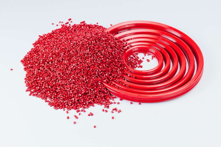
Matching Resin Systems to Your Operating Environment
Resin selection is your primary defense against environmental degradation. Polyester resins work well for general applications with mild exposure. Vinyl ester resins outperform polyester in chemical and moisture environments. Epoxy systems offer superior performance in certain high-demand applications.
UV stabilizers and protective surface veils extend service life in outdoor applications. Ask about these options when specifying rods for exposed installations. The added cost is typically small compared to the cost of premature replacement.
For unusual or particularly aggressive environments, custom resin formulations may be appropriate. Work with your pultruder to develop specifications tailored to your exposure profile.
Addressing Stress Concentrations and Connection Design
Holes, notches, and sharp corners concentrate stress and accelerate both static and fatigue failure. Design connections to distribute loads over larger areas and to avoid abrupt changes in geometry.
Sealed ends and protected holes prevent moisture and chemical ingress at vulnerable locations. Specify end sealing and hole treatment when ordering rods that will be cut or drilled.
Torque limits for clamped connections prevent crushing damage. Fiberglass composites are strong in tension but can be damaged by excessive through-thickness compression. Include torque specifications in your installation procedures.
Establishing Inspection Intervals Based on Exposure Severity
Regular inspection catches degradation before it becomes failure. Set inspection intervals based on exposure severity—more frequent for harsh environments, less frequent for protected installations.
Define acceptance criteria for each inspection point. What level of chalking is acceptable? How much discoloration triggers replacement? Clear criteria ensure consistent decisions and prevent both premature replacement and delayed action.
Document inspection findings to track degradation trends. Components that degrade faster than expected may indicate specification problems that affect other installations.
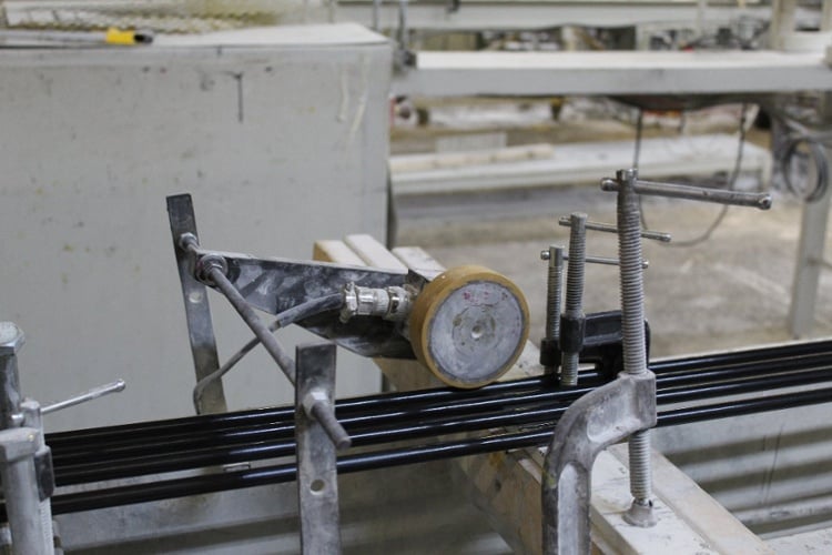
Working with Custom Pultruders for Enhanced Durability
Custom pultrusion offers advantages that standard off-the-shelf products cannot match. When your application involves unusual exposure conditions, tight tolerances, or specific performance requirements, custom manufacturing delivers better results.
Tencom specializes in serving smaller customers with lower minimum quantities and more tailored services than large-volume pultruders typically offer. This focus on custom work means your specific requirements receive attention throughout the design and manufacturing process.
Custom research and testing capabilities set some pultruders apart from commodity suppliers. The ability to validate performance under your actual service conditions reduces the risk of specification errors that lead to premature failure.
Questions to Ask Your Fiberglass Rod Supplier About Durability
What resin systems do you offer, and which is recommended for my exposure conditions? Understanding your options helps you make informed choices rather than accepting default materials.
What UV protection options are available? Surface veils, UV-stabilized resins, and pigmentation strategies all contribute to outdoor durability. Know what's included and what costs extra.
Can you test samples under conditions that simulate my service environment? Accelerated aging tests and exposure simulations validate performance before installation.
What quality documentation comes with your products? Traceability, test reports, and certification records support failure investigation if problems occur and demonstrate manufacturing consistency.
In Conclusion: Building a Systematic Approach to Fiberglass Rod Failure Prevention
Root-cause analysis transforms a failure event into a learning opportunity. By systematically investigating what went wrong and why, you develop the knowledge to prevent similar failures in future installations.
The field-to-lab workflow described in this guide provides a structured approach: map exposure conditions, conduct a visual inspection, select targeted tests, confirm the root cause, and apply the findings to improve specifications. Each step builds on the previous one, narrowing possibilities until you reach a defensible conclusion.
Working with pultruders who understand failure mechanisms and offer custom solutions helps you move from diagnosis to prevention. When your supplier can test materials under your specific conditions and engineer products for your environment, you reduce the gap between specification and performance.
Premature failure is not inevitable. With proper specification, regular inspection, and systematic failure analysis when problems occur, you can achieve the long service life that pultruded fiberglass rods are capable of delivering.
FAQs about Fiberglass Rod Failure Analysis and Testing in 2026
What is the most common cause of premature fiberglass rod failure?
Environmental degradation from UV exposure, moisture absorption, or chemical attack causes most premature failures. These mechanisms often work together—UV damage creates entry points for moisture, which accelerates further degradation.
Tencom engineers custom pultruded fiberglass rods with resin systems and surface protection matched to your specific environment, reducing the risk of these common failure modes.
How can I tell if UV damage caused my fiberglass rod to fail?
Surface chalking, color fading, and fiber bloom indicate UV degradation. Run your finger across the surface—white powder on your skin confirms chalking. FTIR spectroscopy testing can quantify the chemical changes UV exposure causes in the resin matrix.
What tests confirm moisture-related damage in fiberglass composites?
Gravimetric analysis measures water content by weighing samples before and after drying. Short beam shear testing evaluates interface integrity. DSC testing measures glass transition temperature, which drops when moisture plasticizes the resin.
Tencom's testing capabilities include these and other methods for assessing moisture damage in pultruded products.
How does Tencom help prevent premature fiberglass rod failure?
Tencom offers custom research and testing abilities that help match resin systems and fiber reinforcements to your operating environment. Lower minimum quantities make custom solutions accessible for smaller projects. Design and engineering support help you specify products that meet your actual service conditions.
What inspection schedule should I follow for fiberglass rod installations?
Inspection frequency depends on exposure severity. Harsh outdoor or chemical environments warrant annual inspection at minimum. Protected installations may need only periodic checks every few years. Document findings and track degradation trends to refine your schedule over time.
Can fatigue failure occur in fiberglass rods under normal operating loads?
Yes, fatigue damage accumulates under repeated loading even when individual loads remain below the ultimate strength. Fatigue life depends on load magnitude, frequency, and the presence of stress concentrations. Proper connection design and load distribution significantly extend fatigue life.